Our objective is to execute specialty foundation projects, soil improvement all geotechnical applications in the construction area, in Venezuela and overseas. Our project list includes subway stations, railroads, bridges, tunnels, expressways, dams, etc. as well as industrial facilities, power plants, petrochemical complexes, refineries and others. Last but not least, Cimientos BYA , S.A. has been involved in the construction of large commercial and residential projects in Venezuela and abroad.
Cimientos BYA , S.A. usually works as a General Contractor or specialized subcontractor to the General Contractor or to the EPC Contractor.
1. Structural Diaphragm Walls
1.1 Berlin Wall
In this technique, parts of the retaining wall ( soldier piles, cast-in-place or precast columns ) are built before the excavation begins by means of the passive earth pressure (at the toe) and the active earth pressure (multiple tie-backs or struts) . When these elements are in place, the excavation comes in stages and as it advances, precise anchors are immediately installed on the soldiers previously built. In the spaces between the piles, projected cement (shotcrete), prefabricated concrete elements or steel beams can be installed.
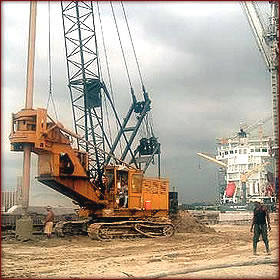
1.2 Concrete Diaphragm Walls
There are a great variety of concrete diaphragm walls, these can be armed (structural) or not. Within the armed diaphragm walls (structural), we have the retaining walls excavated under bentonite mud, used mainly to contain the soil once begun the excavation, being able to support great axial loads. As far as the nonstructural walls, these can be made for the containment of water flows, and to protect highly contaminated zones.
The concrete diaphragm walls are excavated from the surface by means of an excavation clamshell, in thickness that goes from 0.50 m to 1.50 m . As far as the depths, they can reach 50 m. In the cases where phreatic level is present, and where watertightness of the excavation is important, water stop joints can be installed.
In order to guarantee the stability of the structural walls, anchors are installed, in anticipated soldiers as the soil excavation process is made. The anchors can be provisional or definitive, depending on the later use of the wall.
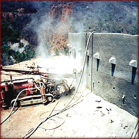
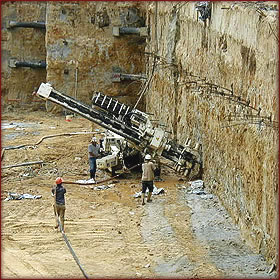
1.3 Shotcrete walls
These are retaining structures, which can be used for slope protection, or as support for the excavation of structures under earth (basements, underground stations such as subways, etc) . Depending on the use, the screens can or cannot contain anchors, and these can be provisional or definitive according to the case. The construction of screens, takes place as the soil excavation progresses, outlining and combing it manually. After that, are reinforced by means of meshwork or steel skeleton, following with the shotcrete over the surface until the required thickness is reached, this technique mold to the surface allowing variable shapes.
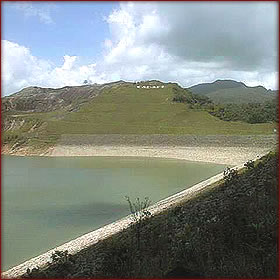
2. Watertight Slurry Walls
These walls are built using the same technique as for Concrete Diaphragm Walls, but unlike them, these walls are constructed without armors and with a "plastic" deformable concrete, which results from the mixture of cement, well graded aggregates and bentonite.
The fluid of perforation for these cases is a bentonite-cement grout, instead of the usual bentonite mud. The bentonite-cement grout constitutes the waterproofing material of the wall after the setting.
Walls thickness goes from 0.50 m , being able to reach 1.20 m , and with a depth that can reach 50 m . These walls are particularly useful in dam constructions, where the watertightness plays a special role.
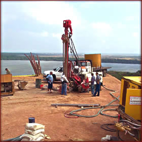
3. Deep Foundations
3.1 Piles
These elements are able to support great precise loads. They can be excavated in the dry or with bentonite mud when the phreatic level is high. As far as the diameter, they can be made from 0.55 m to 2.00 m . The excavation is made by means of rotation equipment, with buckets or spirals; and great depths can be reached.
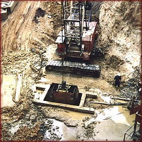
3.2 Barrettes
Barrettes are foundation elements, where the basic characteristics rely in the form and the way of the excavation. They are recommended in presence of elevated loads, since they have much greater resistance to the horizontal efforts, than circular piles of the same section. The excavation is made with clamshell, and dimensions can be:
The possibility to voluntarily increase its surface, grants them an insurmountable characteristic. Compositions that can be obtained are, simple barrettes, in cross (+) and H.
3.3 Micropiles
Are foundation elements, whose technique is derived from the conception of the soil anchors. They are elements of small section (100 to 200 mm ) and of low to average capacity.
The mechanical characteristics obtained from micropiles, allow them to support indifferently, as much compression as traction.
Micropiles supersede, technically and economically, from any other solutions for the foundation of building and bridges, underpilling foundations, metallic towers foundations, containment of excavations (screens of micropiles) and reinforcement of soil, as well as in all the cases of:
· Low and scattered loads.
· Natural ground is heterogeneous or contains obstacles such as boulders or early foundations, etc.
· Conditions are difficult for setting up and moving equipment (tight site or neighborhood).
· Compression and traction loads alternate.
Micropiles are executed with light and versatile hydraulic equipment of high power, which allows any inclination of the elements to found. They are excavated with rotation in all types of soils and materials (rock, concrete), with casing or without it, with water or bentonite, everything according to the necessity.
4. Grouting for Consolidation and Waterproofing
This method of soil improvement, consists of injecting within a more or less permeable mean, a material that can be pumped (liquid, suspension, emulsion, mortar), called grout.
The "mean" to inject, can be the natural or artificial soil (masonry, concrete, etc.), and its primary target is to improve the properties of the material (to improve its mechanical resistance, or to reduce its permeability).
Grouting for Consolidation and Waterproofing, is one of the specialties of Cimientos BYA S.A. This technique has been used in dams with classic injections, of waterproofing curtains with cement grouts; for tunnels in urban zones, grouting for the consolidation of fine soils with chemical grouts, as well as the accomplishment of binary and tertiary grout injections ( cement - clay bentonite), in alluvial soils.
5. Ground Improvement
Ground improvement is another Cimientos BYA S.A. specialty, in which diverse techniques are used to solve foundations problems in soils with terrible mechanical characteristics, and in some cases, they can be used to avoid in particular, the possible risk of sand liquefaction by the action of an earthquake. The methods that our company can offer are the following:
5.1 Compaction Grouting
This technique is used to improve the ground capacity (especially of highly saturated sands, mud and clays).
This method is used in the same cases of compaction columns, nevertheless, those are used previous to the construction time - when more efficient - and the compaction grouting, when the construction has already taken place.
The methodology consists in making the soil perforation, using drill bits and water, leaving the casing tube. When the design depth is reached, the injection of the mortar begins, which must be solid enough, but plastic simultaneously.
The mortar, which is pumped through the casing left in the perforation, makes the soil compaction by the pressure practiced against it.
This method is especially useful to improve the ground capacity of freeways and constructions already made, where the need to improve the capacity of the soil, is required.
5.2 Dynamic Compaction
This is a technique that allows to globally improving the soil from the surface, and is especially useful for industrial and commercial developments.
The procedure used, consists on dropping great weights of several dozens of tonnes, repeatedly towards the soil from a high altitude.
Before getting to work, a complete study of the soil is made, where the weight and the height of the load are determined, as well as the location of each point of compaction.
6. Soil Anchors
Soil Anchors are elements that transmit the tensile forces applied to them to a competent soil. The anchors consist of three (3) parts or elements:
· The head that transmits the force of the anchor to the structure via the bearing plate.
· The free length of tendon, that goes from the head to the near end of the anchorage.
· The bulb of anchor, which is the length of the tendon subject to the force of tensile transmitted to the competent soil, by means of the injection grout.
The loads of tension of the braces vary from 15 to 120 tons, with perforations from Ø 2" to Ø 5". The anchors can be active or passive, according to the time when they are tightened (before or after the structure is made).
According to the duration for which it has been designed the anchors can be
· Provisional: They are soil anchors that are mainly executed in constructions to make the excavation of the soil, and they are applied on screens or strained walls.
The duration or time of life is of 24 months maximum, mainly because the steel of the brace in the free part is not protected against corrosion.
· Definitive: They are anchors that are made for permanent support works, and whose loads will not be compensated.
In this case, the anchor design is executed by means of a plastic or metal tube that will contain its armor in all its length, and which will be injected with grout, which will prevent the steel to become in contact with the soil.
The head of the brace is protected with a plastic or metal cover, and in last case it will be covered in concrete.
7. Protection of the Environment
Within the protection of the environment, Cimientos BYA S.A., offers techniques that allow to isolate highly contaminated zones, avoiding that the infiltrations of emanated toxic products reach the surrounding soils, and contaminate underground waters.
As an example, Cimientos BYA S.A. in 1987, completed a job to confine an industrial waste disposal zone, characterized by a high level of mercury contamination, in the Petrochemical Complex at Morón. This job required a very specific containment technique.
The hydraulic containment for the site was achieved using a watertight screen which surrounded the contaminated zone, and which penetrated into a deep impermeable ground layer.
The screen isolates the mercury deposits from the aquiferous soil which has a gradient running down towards the sea.
Moreover, because it is situated downstream from a factory which manufactures acids, the screen must resist effluents loaded with phosphoric and sulphuric acids with a pH lower than 2.
To satisfy these particular and constraining criteria, the material used to form the screen was made up for a plastic concrete without cement, with a very carefully designed grading, comprising fine siliceous sand, bentonite and silicate.
This concrete, with a density of 1.95, gives an initial permeability of 2 to 7 x 10 -10 m/s before contact with the acid. The acid escape diminishes the permeability to a value inferior to 10 -10 m/s. The screen is guaranteed for a life of 20 years.
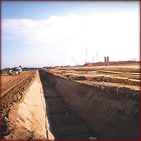
8. Drainages
8.1 Perforated Drains
Drains are often used when works (land fill, side slopes, etc.), are made in quite impermeable soils (clays, the slime, argillaceous sands, vegetal earth, etc.), since these can become unstable, due to the underground water presence contained in one or more aquiferous.
The use of horizontal drains, allows to substantially improving the stability of the soil, capturing and evacuating the water contained in the aquiferous. These drains are made within the soil, with light rotation equipment, and equipped with plastic pipes, reaching lengths of 100 m.
Typical use of this technique has been successfully made in dam works, as well as in side slopes works.
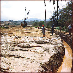
8.2 Drainage Trenches
This specialty is also derived from the Concrete Diaphragm Walls’ technique; it allows making drainage trenches of important depth and development as it is required, in order to drain circulations and water exits that endanger the stability of the work.